Smart Actuators
An all-in-one package which includes a BLDC Motor, Harmonic Gearbox, and Motor Driver, seamlessly integrated for easy use; simply connect it to the NLink Adapter via Controller Area Network (CAN) Bus connection and leverage our Software SDK to precisely control and command its movements according to your needs.
Models and Specifications
| NH-S2 | NH-S3 | |||
| Voltage / V | 48 | |||
| Gear Ratio | 50 | 100 | 50 | 100 |
| Rated Torque / Nm | 28 | 55 | 45 | 90 |
| Speed at Rated Torque / RPM | 50 | 20 | 50 | 20 |
| Peak Torque / Nm | 43 | 105 | 125 | 200 |
| Peak Speed / RPM | 60 | 30 | 60 | 30 |
| Rated Current / A | 5.5 | 5.2 | 8.2 | 8.1 |
| Peak Current / A | 8 | 10 | 24 | 18 |
| Weight / kg | 1.3 | 2.0 | ||
| Output Load Specifications | 2 x NSK 6808ZZ (Load specifications as per bearing) | 2 x NSK 6809ZZ (Load specifications as per bearing) | ||
| Sensors | 1 x 16-bit Absolute Encoder on the output side 1 x 4096 CPR Incremental Encoder on the Motor Side 1 x Motor Thermistor | |||
Drawing


All dimensions are in mm
| NH-S2 | NH-S3 | |
| L | 122 | 124 |
| L1 | 44 | 4 |
| L2 | 2.5 | 2.5 |
| D1 | 38 | 48.5 |
| D2 | 53 | 64 |
| ID | 12 | 16 |
| OD | 72 | 90 |
| Rotor | 8 x M4 (10 mm Depth) Tapped Holes PCD Ø 27 | 8 x M5 (10 mm Depth) Tapped Holes PCD Ø 34 |
| Stator | 8 x M3 (8 mm Depth) Tapped Holes PCD Ø 62 | 8 x M4 (8 mm Depth) Tapped Holes PCD Ø 75 |
Download the CAD files for the acutators here: Smart Actuators v1.0
Hardware
The package consists of a gearbox, BLDC motors, and a motor driver, all integrated into a single unit. Power supply and communication with the actuator are managed via connectors located at the rear. The status of the actuators is displayed through LED indicators. The motor driver operates the BLDC motors according to commands received through the CAN bus interface.
- Ensure that the load connected to the actuator falls within the specified static and dynamic load limits of the output bearings.
- Ensure that the actuator is free to rotate atmost 8° degrees in one direction when it starts up to complete the Startup Calibration Process. Make sure to verify that this rotation of atmost 8° degrees in one direction of the actuator is acceptable for your application.
Connections
The actuator has three sets of connectors: two are designated for the daisy chainable CAN interface, while the third is used for power input.
| Connector | Part | Pins | Pin Description | Notes |
| C1 | CAN Connection 1 | 1 | CAN_L CAN Low Signal | CAN Bus Connection: JST-PH 2mm Connector |
| 2 | CAN_H CAN High Signal | |||
| C2 | Power Connection | 1 | GND Ground / Negative Terminal | Power Connection: XT30 Connector |
| 2 | + Positive Terminal | |||
| C3 | CAN Connection 2 | 1 | CAN_L CAN Low Signal | CAN Bus Connection: JST-PH 2mm Connector |
| 2 | CAN_H CAN High Signal |
Power Connection
The actuator requires an XT30 connector for power input, with a rated supply voltage of 48V. Ensure that the wiring used is rated for the current specified in the actuator's technical specifications.
- DC power input pins can't tolerate reverse polarity, please verify all power connections before energizing the driver
- Never hot plug the driver, make sure that the power connections are connected before turning on the power.
CAN Bus Connection
The actuator features a daisy chainable CAN bus interface with two CAN ports. One port is designated for incoming CAN bus connections from the main device, while the other port is intended for connecting to the subsequent device in the bus chain. A 2-pin JST PH connector with a 2mm pitch is suitable for both CAN ports.

If the actuator is the final component in the CAN bus chain, a 120 Ω termination resistor must be placed at the last CAN port of the last actuator. Failure to install the termination resistor may lead to communication errors.
LED Status Indicators
The device features three connectors for power and CAN bus connections, and it includes three LED indicators at the bottom that display the status of power, communication, and errors.
| Part | Notes |
| POWER LED | Green LED indicates the power status and will light up when power is properly supplied. |
| CAN STATUS LED | Orange LED indicates CAN communication status and will blink when communication is occurring continuously. |
| ERROR LED | Red LED will light up to indicate the presence of any errors. |
Software
The actuator has an inbuilt motor driver that can be controlled through a CAN Bus interface. By using our NLink Adapter, it can also be connected via USB, allowing for configuration and control through the NMotion CLI Tool and NMotion Transport Library.
The API functions that can be used with the actuator can be found here: Actuator API documentation
Hardware Configuration
CAN Bus Configuration
The actuators utilizes a daisy chainable CAN bus for control. If multiple devices are present on the CAN bus, ensure that a unique CAN Node ID is assigned to the actuator. The allowable values of CAN Node ID is in the range of 0 to 127. The default CAN Node ID is 0 and must be modified to avoid communication conflicts.
On setting the CAN Node ID, the motor controller will automatically save the CAN node ID and reboot.
The API functions involved in this configuration are as follows:
Power Configuration
Voltage Trigger Levels
The motor driver features undervoltage and overvoltage protection mechanisms to ensure the safe operation of the actuator and other components. If the bus voltage drops below the undervoltage threshold or exceeds the overvoltage threshold, the driver will enter idle mode and generate a DC_BUS_UNDER_VOLTAGE or DC_BUS_OVER_VOLTAGE error, respectively.
By default the under voltage level is set to 10 V and the over voltage level is set to 56 V.
The API functions involved in this configuration are as follows:
Maximum Regeneration Current Trigger Level
The amount of current that can be safely dumped by the actuator into the power bus can be specified. This ensures that the power supply remains protected from excessive current dumping. It is recommended to use a regeneration current clamp circuit which has a brake resistor when powering the driver with a power supply that does not support power dumping. In the case of battery power, regenerative braking allows the battery to recharge itself by utilizing the reverse current.
If the regeneration current exceeds the configured maximum limit, the driver will enter idle mode and generate a DC_BUS_OVER_REGEN_CURRENT error. This condition can arise from either a saturated brake resistor on the regeneration clamp circuit or excessive current dumping into the power bus when there is no regeneration current clamp circuit.
Saving the configuration is necessary for this configuration to take effect in the motor driver.
The API functions involved in this configuration are as follows:
Thermal Limit Configuration
The motor driver uses an onboard NTC thermistor to measure it's temperature during the operation. The configuration for thermal limiting using this on-board thermistor cannot be changed, the driver will start limiting the current once the board temperature reaches 110°C. When the board temperature reaches 120°C, it will turn off the power to the motor and will set the error to FET_THERMISTOR_OVER_TEMP. If this limit is being reached, then it is suggested to add an active cooling mechanism to the actuator body which will help to keep the temperature in safe levels during the operation.
Additionally, the driver also has the motor NTC thermistor connected to it that can be used to limit the motor currents when the motor temperature goes beyond a safe limit. If motor thermal limit needs to be enabled then one needs to configure the upper_limit value (in °C) for the thermal limit. The current limiting will start when the temperature reaches a value of upper_limit - 10 (in °C). When the motor temperature reaches the upper_limit value, the driver will turn off the power to the motor and will set the error to MOTOR_THERMISTOR_OVER_TEMP . If this limit is being reached, additional cooling is recommended to help maintain the motor's temperature within safe limits during operation.
The API functions involved in this configuration are as follows:
Controller Configuration
The motor driver in the actuator has a cascading style controller with cascaded position, velocity and current control loops. When the control mode is set to position control or trajectory control, all of the cascaded controller runs. When running in velocity control mode, the position control part is removed and the velocity command is directly given to the velocity controller. Similarly, in torque control mode, only the current controller loop runs.
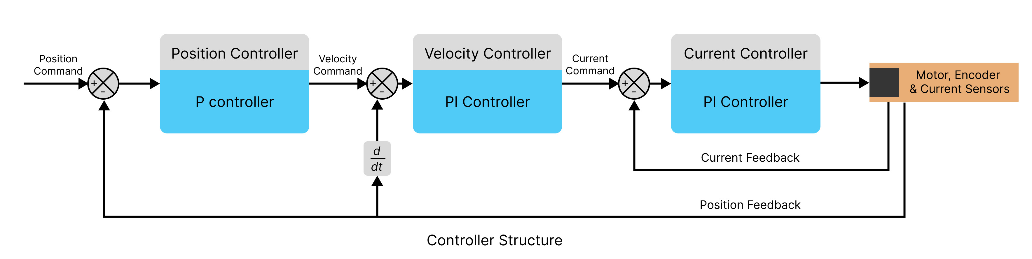
The controllers used in each of the loops is a variation of PID Controllers
Position Control Loop
Its a proportional controller with a single gain value (pos_gain). The output of the controller, velocity_command is calculated as follows:
velocity_command = pos_gain * (position_command - position_feedback)
Velocity Control Loop
Its a proportional-integral controller with a single gain value (vel_gain) and a single integrator gain (vel_integrator_gain). The output of the controller, current_command is calculated as follows:
vel_integral += vel_integrator_gain * (velocity_command - velocity_feedback)
current_command = vel_gain * (velocity_command - velocity_feedback) + vel_integrator_gain * (vel_integral)
Current Control Loop
Its a proportional-integral controller with a single gain value (current_gain) and a single integrator gain value (current_integral), the gain values of this loop is calculated based on the motor's phase parameters (phase resistance and phase inductance) and a current controller bandwidth parameter.
current_gain = current_control_bandwidth * motor_phase_inductance
current_integrator_gain = current_gain * (motor_phase_resistance / motor_phase_inductance)
current_integral += current_integrator_gain * (current_command - current_feedback)
motor_command = current_gain * (current_command - current_feedback) + current_integral
The gain values of the loop can be changed according to the needs of the application. If the gains cause an instability in the system, then the driver will throw a UNSTABLE_CONTROLLER_GAIN error.
The API functions involved in this configuration are as follows:
Actuator.setPositionControllerGain(position_gain: float)Actuator.getPositionControllerGain()Actuator.setVelocityControllerGains(vel_gain: float,vel_integrator_gain: float)Actuator.getVelocityControllerGains()Actuator.getCurrentControllerGains()Actuator.setCurrentControllerBandwidth(bandwidth: float)Actuator.getCurrentControllerBandwidth()
Saving Configuration
Upon completing the configuration process, the settings can be saved to the motor driver's non-volatile memory. This ensures that the configurations are retained even after a power cycle or device restart. Saving the configuration will trigger an automatic reboot of the driver.
The following configurations in the driver are saved:
- CAN Bus Configuration : CAN Node ID of the device.
- Power Configuration : Voltage trigger levels (under voltage and over voltage trigger levels), Maximum regeneration current trip level.
- Thermal Limit Configuration: Thermal upper limit.
- Controller Configuration: Control Loop parameters (position gain, velocity gain, velocity integrator gain, current controller bandwidth) & Control Mode without the commanded value.
The configuration data is stored in the microcontroller's onboard EEPROM memory. To prolong the memory's lifespan, it is recommended to limit the frequency of configuration updates, as EEPROMs have a finite number of write cycles.
The API functions involved in this configuration are as follows:
Operation
Connection
The actuator uses a CAN bus to retrieve data and send commands to the motor driver. The motor driver can be controlled either through a native CAN interface or connected to a PC via USB using an NLink Adapter. Regardless of the interface used, the NMotion Transport Library can be used to control the driver.
Startup Calibration Process
Upon powering up, the motor inside the actuator will rotate atmost 8° degrees in one direction to complete the incremental encoder calibration process. As a result, the actuator will reach a non-zero output position once the calibration is complete. Additionally, make sure to verify that this rotation of actuator is acceptable for your application.
- Allow the actuator to complete the startup calibration process before issuing any commands. Sending commands before the calibration is finished may result in
INVALID_STATEerror. - Avoid applying excessive torque to the actuator during startup, as this could cause the startup calibration process to fail and result in a
SPINOUT_DETECTEDerror once the actuator enters closed-loop control.
Control Modes
The motor driver supports various control modes. The reference frame for these control modes is the actuator's output, which is calculated by using the motor encoder value and gearbox ratio of the actuator.
The different control modes in which the driver can run are as follows:
- Idle Mode: In this mode the motor will not be in any control loop, and it will be free to turn.
- Position Control Mode: The motor moves at a specified velocity to a particular position as commanded.
- Parameters:
- Position (in degrees) to which the motor should move
- Velocity (in degrees per second) at which the motor should move.
- Parameters:
- Velocity Control Mode: The motor moves at a particular velocity as commanded.
- Parameters:
- Velocity (in degrees per second) at which the motor should move.
- Parameters:
- Torque Control Mode: The motor current is controlled so that a particular amount of torque remains applied as commanded. The motor velocity is also limited during this motion. Once the motor reaches the maximum motor velocity then it will start limiting the motor currents to make sure the velocity remains in the specified range.
- Parameters:
- Torque value (in Newton-meter) which the motor should supply.
- Maximum velocity limit (in degrees per second) at which the motor should move.
- Parameters:
- Trajectory Control Mode: The motor moves to a particular position in a trapezoidal trajectory pattern as commanded.
- Parameters:
- Position (in degrees) to which the motor should move.
- Max velocity (in degrees per second) of the motor that it should reach during the motion.
- Acceleration rate (in degrees per second2) of the motor which decides how fast the motor should reach the max velocity.
- Decceleration rate (in degrees per second2) of the motor which decides how fast the motor should reach the zero velocity.
- Parameters:
- Velocity Ramp Control Mode: The motor moves at a specified velocity as commanded. But the specified velocity is reached with a slow ramp as specified by the ramp rate.
- Parameters:
- Max velocity (in degrees per second) at which the motor should move.
- Ramp rate (in degrees per second2) of the motor which decides how fast the motor should accelerate/deccelerate to reach that commanded max velocity value.
- Parameters:
The API functions involved for this control modes are as follows:
Actuator.setDeviceToIdle()Actuator.setDeviceToActive()Actuator.setPositionControl(angle: float, degrees_per_seconds: float)Actuator.setVelocityControl(degrees_per_seconds: float)Actuator.setTorqueControl(torque: float, degrees_per_second: float)Actuator.setTrajectoryControl(angle: float, degrees_per_seconds: float, accel_rate: float, decel_rate: float)Actuator.setVelocityRampControl(degrees_per_seconds: float, ramp_rate_degrees_per_second: float)
Zero Position
The motor driver enables zero position setting for the actuator by using the absolute encoder at the output. It can set the actuator's current position as zero, relying on an available absolute encoder for precise position calculation.
To ensure the zero position remains the same after a driver reboot, saving the configuration after setting the zero position is required.
The API functions involved with setting the zero position are as follows:
Getting Other Datapoints
The motor driver includes a multitude of sensors connected to it. It also has various software states that determine the operation of the actuator. There are specific API functions that can be used to get sensor data and different software states from the driver.
The API functions involved with getting various data points are as follows:
Versioning
Encoder Data
Actuator.getOutputPosition()Actuator.getOutputVelocity()Actuator.getOutputAcceleration()Actuator.getOutputTorque()Actuator.getMotorPosition()Actuator.getMotorVelocity()Actuator.getMotorAcceleration()Actuator.getMotorTorque()Actuator.getMotorEncoderRawData()Actuator.getOutputEncoderRawData()
Temperature
Electrical
Actuator.getBusVoltage()Actuator.getBusCurrent()Actuator.getIdqCurrents()Actuator.getMotorPhaseCurrents()Actuator.getMotorPhaseParameters()
Miscellaneous
Error Handling
During operation there are cases in which the motor driver will throw an error in case of wrong configuration or other operational scenarios. When the driver throws an error, the Error LED will turn ON and then the actuator will be set to an idle state. During this time, driver is able to return an error code value for the errors. The value of which can be looked up in the below table to find out what the error means and how to solve it.
When the driver throws an error, the error needs to be manually cleared before the motor can normally run, if the errors are still not cleared then driver reboot would be necessary.
| Error Code | Error | Reason | Troubleshooting |
|---|---|---|---|
| 1 | DC_BUS_UNDER_VOLTAGE | Bus voltage drops lower than the under voltage trip level. Could be caused when the actuator is trying to draw more current than what the power supply can give. | Check the cause of the drop in bus voltage, then adjust the under-voltage trip level if needed. |
| 2 | DC_BUS_OVER_VOLTAGE | Bus voltage goes higher than the over voltage trip level. Could be caused when the dumped regeneration current to the supply is too high, and the supply is not able to handle it. | Check for the cause of the spike in bus voltage, and then adjust the over-voltage trip level if needed. If the cause of spikes is attributed to regeneration current, use an appropriate power supply which will allow you to dump more current or use a regeneration clamp circuit with the required specification |
| 3 | DC_BUS_OVER_REGEN_CURRENT | Regenerative current goes higher than the maximum regen current trip level | Change the trip level value if more current can be dumped into power supply, if not use an appropriate regeneration current clamp circuit with the required specifications. |
| 5 | INVALID_STATE | Motor Driver state is invalid, Possibly caused when actuator is set to closed loop control before the actuator initialised | Make sure to wait for 2 seconds before the acutator is put in closed loop control |
| 6 | ESTOP_REQUESTED | Received emergency stop signal from user | Clear errors and continue. |
| 9 | DRV_FAULT | Low level driver fault | - |
| 10 | FOC_ERROR | Low level control loop fault | - |
| 12 | CURRENT_LIMIT_VIOLATION | Motor current goes higher than the current limit | Check why the actuator is drawing too much current, and if necessary, increase the current limit while ensuring it remains safe for the actuator. |
| 13 | MOTOR_THERMISTOR_OVER_TEMP | Motor temperature is higher than the upper limit | Actively cool the actuator body during operation, and if needed, increase the temperature upper limit while ensuring it remains safe for the actuator. |
| 14 | FET_THERMISTOR_OVER_TEMP | Driver temperature reaches 120 °C | Actively cool the actuator body during operation. |
| 19 | UNSTABLE_CONTROLLER_GAIN | Gain values of the control loop is causing instabilities | Tune the gain values properly. |
| 20 | SPINOUT_DETECTED | Mechanical/Electrical slip between motor and motor encoder | Reduce actuator acceleration / decceleration during actuator motion. Can also be rarely caused by a very high torque during the startup calibration process in which case, reduce the torque acting on the actuator when it starts up and does the calibration process. |
| 255 | UNKNOWN_ERROR | Unknown Error | - |
If you continue to face any other errors or errors even after following the troubleshooting step, make sure to reach out to us.
The API functions involved with error handling are as follows:
Quick Setup
In order to show how a actuator can be easily connected and used, we are assuming that we have a NH-S2 100 Gear Ratio actuator. We will be using NLink Adapter to connect the driver to PC running NMotion CLI tool in Linux (note there won't be any changes in the Windows case as well). We will use the tool to configure and run the actuator
Connection
- Connect the XT30 power connector (Don't hotplug, make sure that the power is OFF).
- Plug in the CAN Bus connections and connect this to NLink Adapter and then connect the Adpater to PC's USB Interface.
CLI Tool Setup
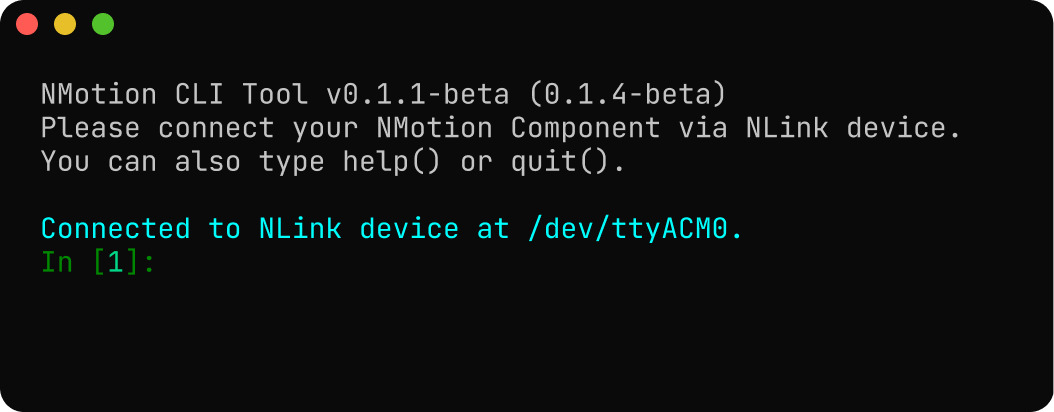
Start the NMotion CLI tool, and plug in your NLink Adapter.
Now turn on your power to the actuator. The actuator will then move incrementally in clockwise and counter clockwise directions to complete the startup calibration process.
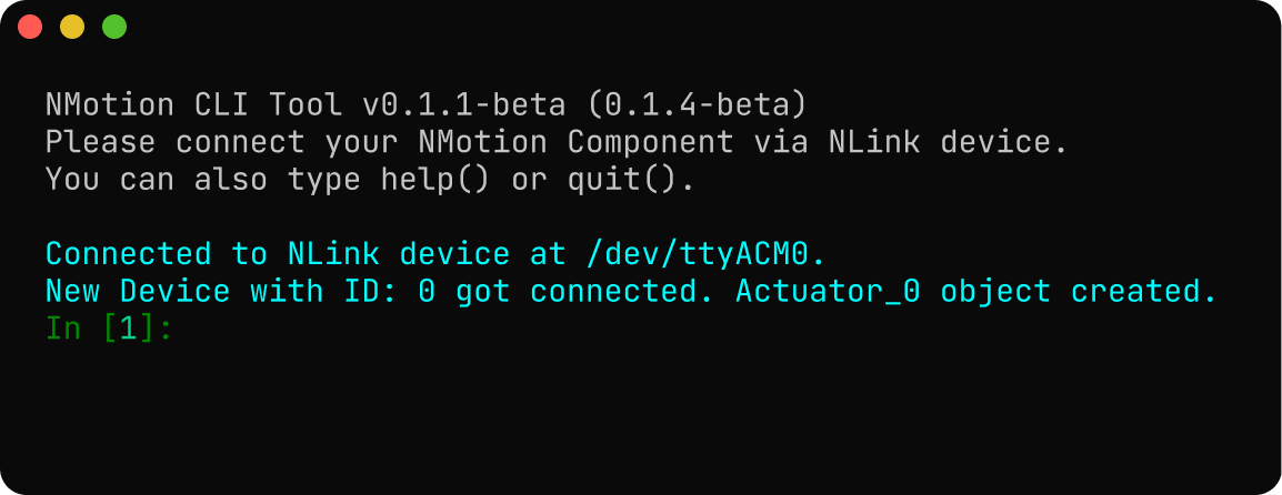
Now you can use the Actuator_0 object to call the relavant Actuator APIs in Python to run and configure the actuator.
Configuring the Driver
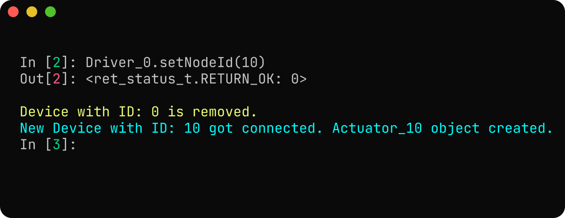
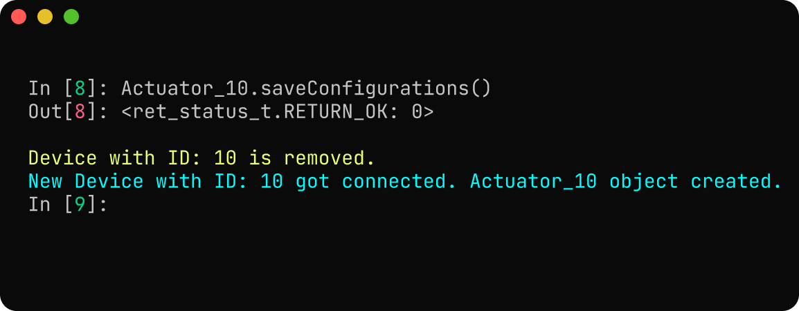
- CAN Bus Configuration: Update the CAN Node ID of the actuator from default value of 0 to 10. On setting the CAN Node ID the device will automatically reboot, which will make the
Actuator_0object to be deleted automatically and creata a newActuator_10object for the driver.
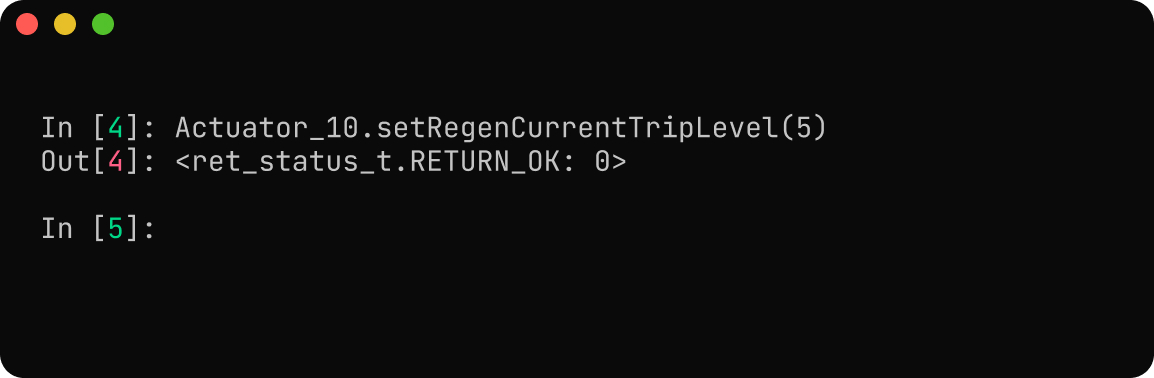
- Power Configuration: Since we are using a 48V actuator, the default values of under voltage trigger level (10 V) and over voltage trigger level (56 V) is fine. We will set the max regeneration current trigger level to 5 A, which the power supply could handle (make sure to check if your power supply could handle the same, it can vary from power supply to power supply).
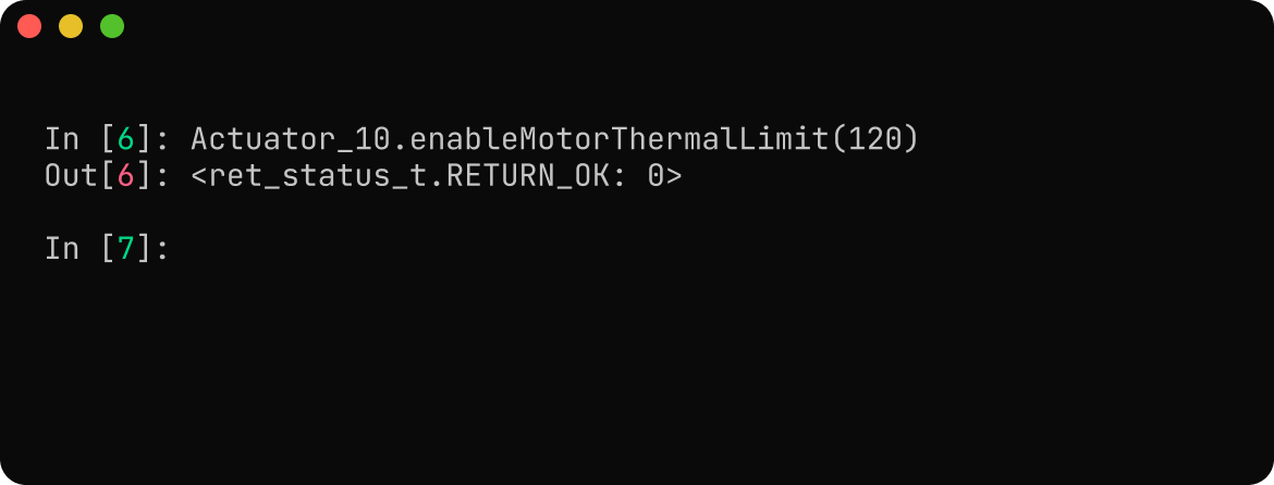
- Thermal Limit Configuration: Set the upper limit for the motor temperature.
- Save Configuration: After configuring all the parameters we need to do a save configuration call to make sure all the parameters are set.
Running the Motor
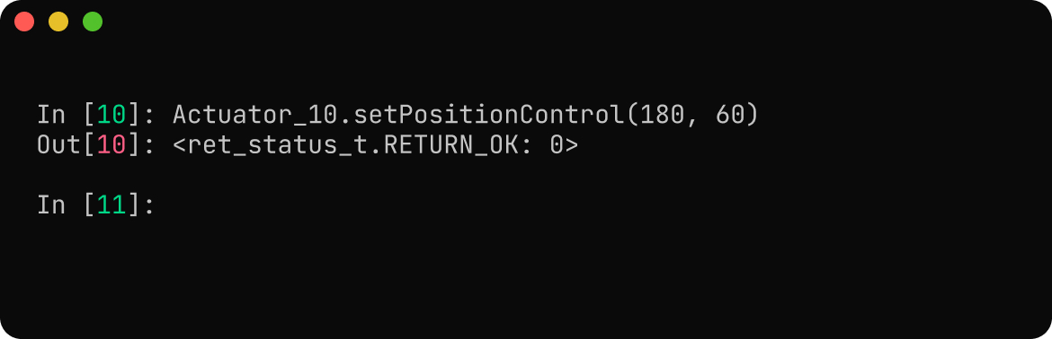
The actuator can be run in various control modes as necessary. Here, we will be running the actuator to a position of 180 degrees at a velocity of 60 degrees per second.
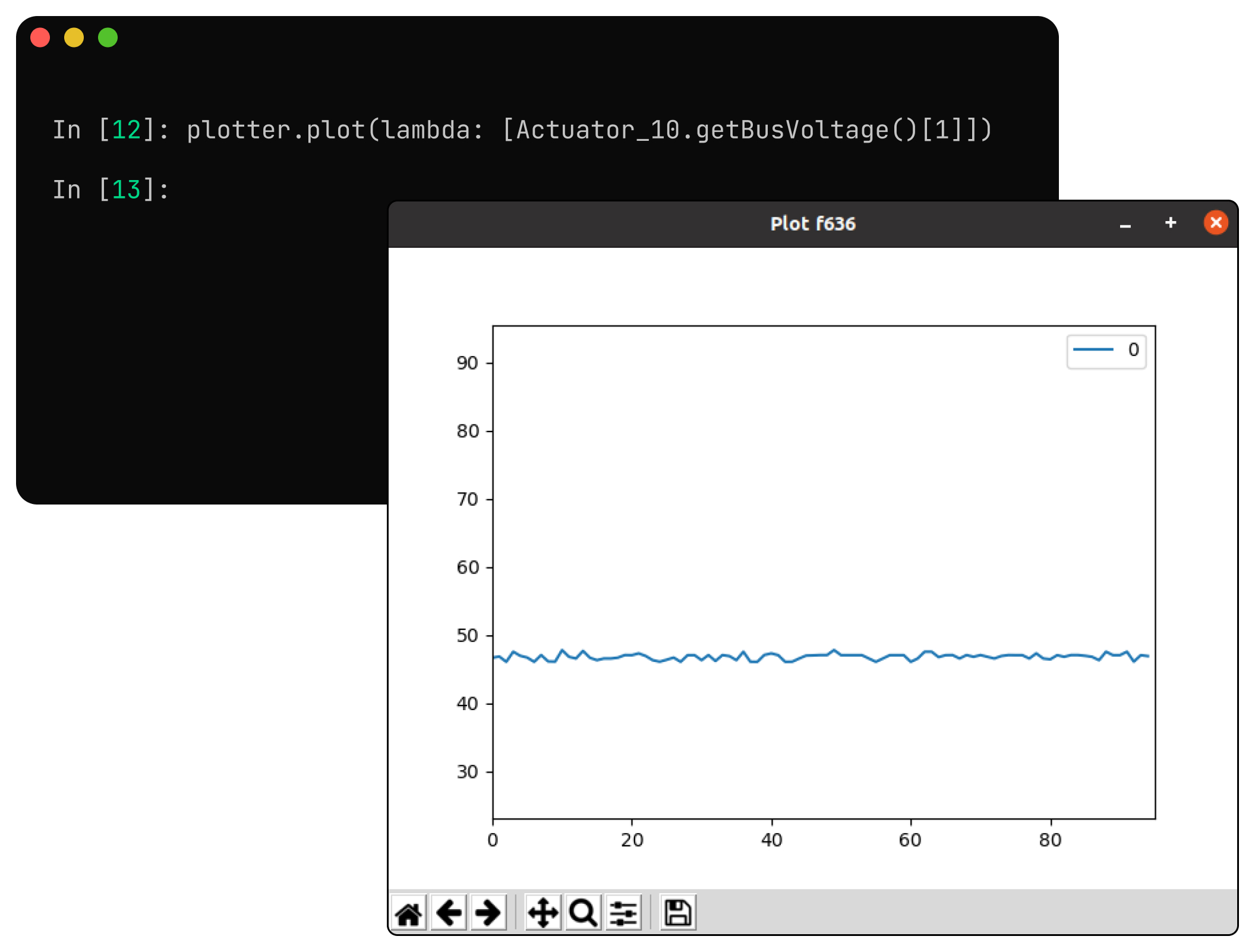
One can also plot the real-time data using the CLI tool as well.
Shutting Down
To shut down the actuator properly, we can command the actuator to come to an idle state and then we can safely turn OFF the driver afterwards.

Customisation and Actuator Development
We can also provide Custom Actuators based on your requirements such as,
- Load and Speed
- Hollow Shaft
- Dual Side Mounting
- Additional Sensor Integration
- Weight and Size Optimisation
- Compatible Fixtures and Couplings
These customisations can be done at a reasonable cost. Our team of experts will help you to achieve your objectives within the constraints of your application. Please contact us to initiate a consultation.