NCoder 732
Description
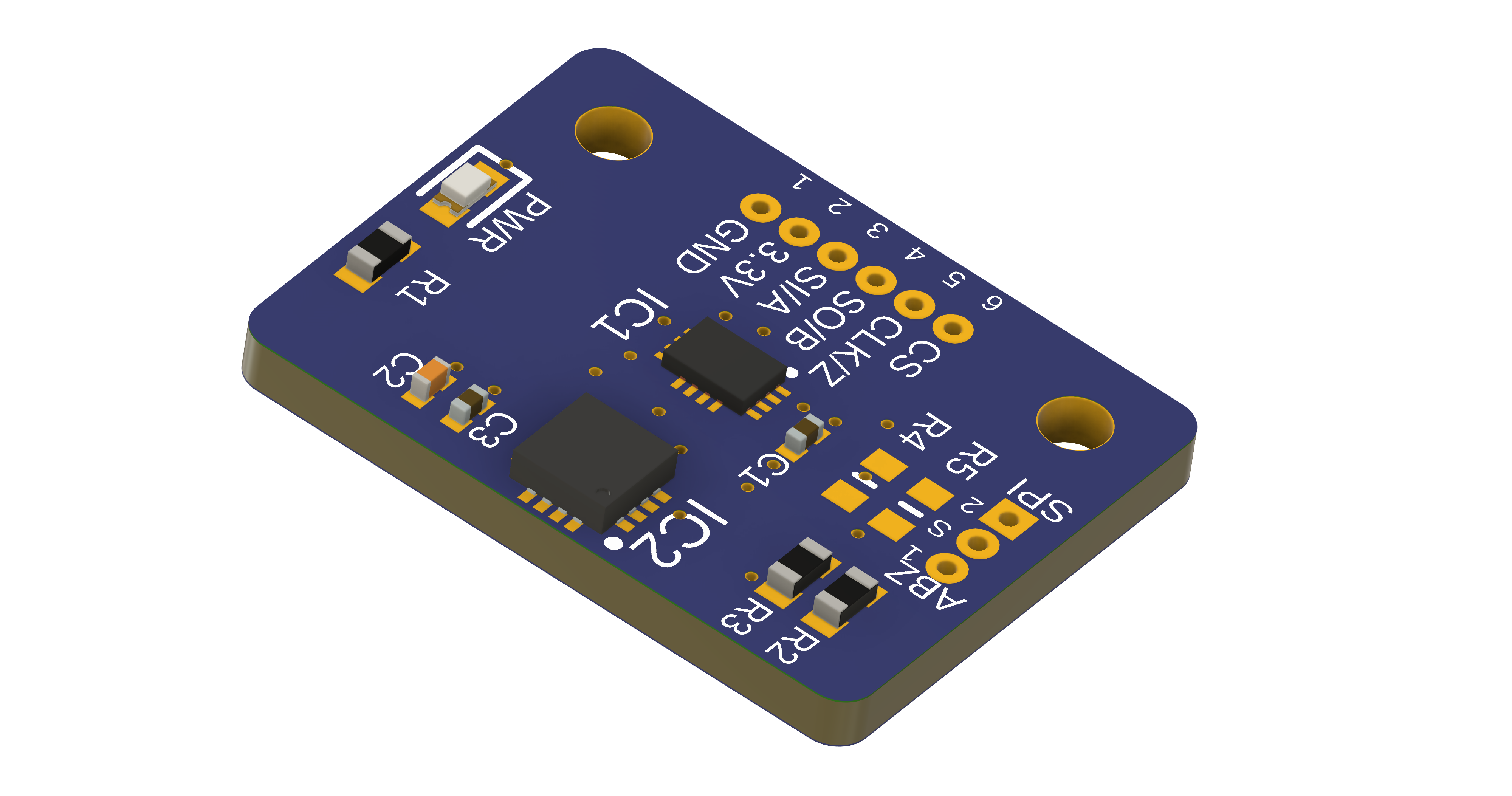
NMotion NCoder732 is a breakout board designed for the MPS MagAlpha MA732 magnetic rotary encoder. It interfaces with an external microcontroller via a single connector located opposite the encoder IC. The MA732 is a high-resolution rotary position sensor for high-speed (up to 60krpm) angle measurement over a full 360-degree range. The MA732 supports a wide range of magnetic field strengths and spatial configurations. It supports a wide range of magnetic field strengths and spatial configurations.
This encoder is suitable for both end-of-shaft and off-axis (side-shaft) mounting applications. To better accommodate off-axis use cases, the encoder IC is strategically placed near the edge of the board, allowing more flexible magnet positioning. It features on-chip non-volatile memory to store configuration parameters such as the zero reference angle, ABZ encoder settings, and magnetic field detection thresholds. Through its SPI interface, a host microcontroller can read up to 15-bit absolute angle position data and program device settings—no dedicated programmer is required. The device also supports a 12-bit incremental ABZ quadrature output, with programmable pulses per revolution ranging from 1 to 1024.
The board includes a mode selection jumper (SEL) and R4/R5 resistor pads, which determines whether the encoder operates in SPI mode or ABZ mode.
This breakout board is ideal for general-purpose angle measurement, high-resolution encoder applications, automotive angle sensing, and robotics.
Connections
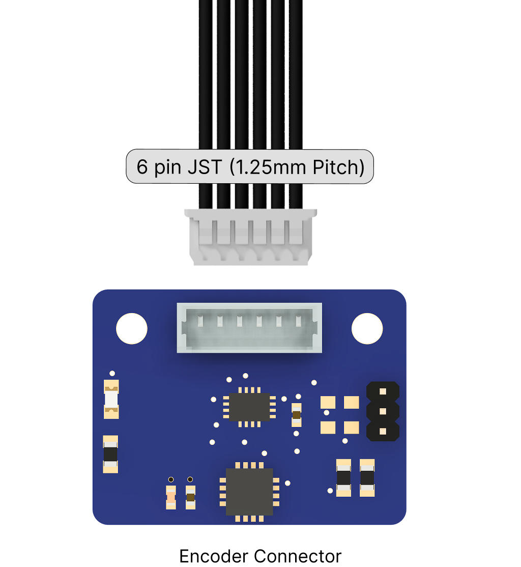
External I/O connections are accessible through a 6-pin JST (2.5 mm pitch) compatible header included with the board.
Pin Configurations and Functions
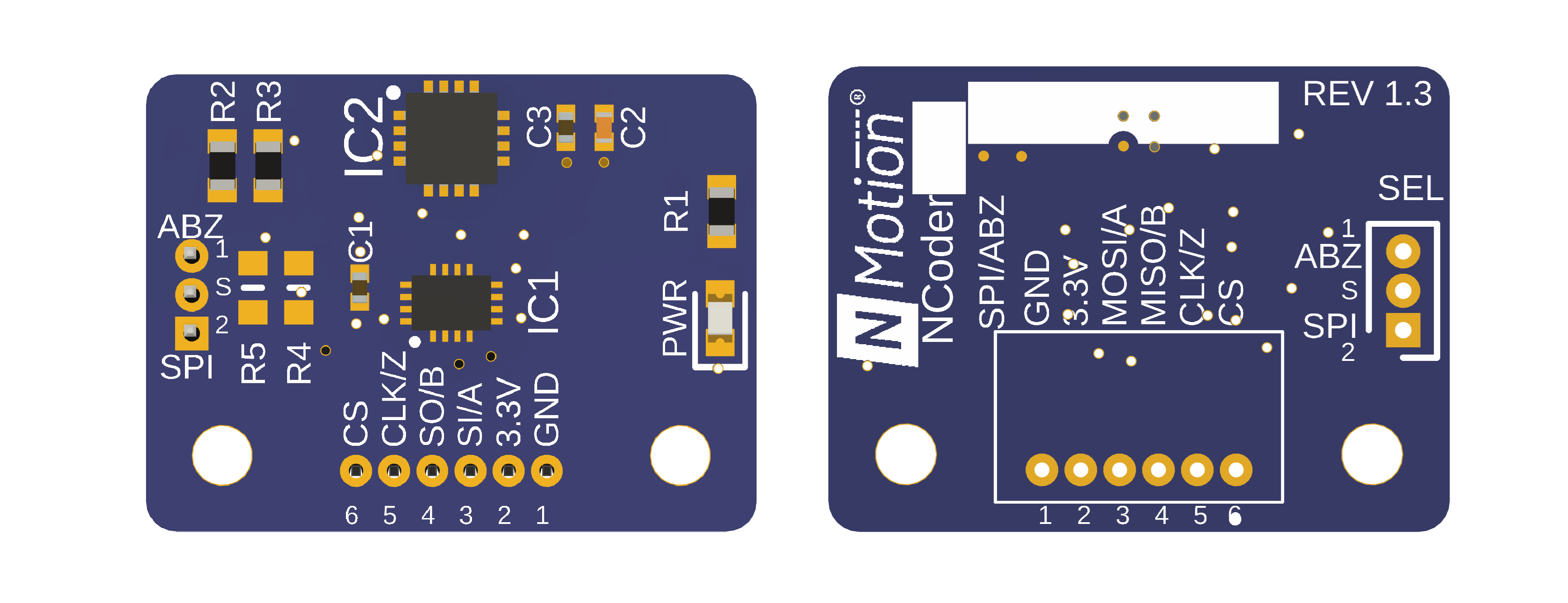
I/O
| Pin | Symbol | Type | Description |
|---|---|---|---|
| 1 | GND | Power Supply | Ground |
| 2 | 3.3V | Power Supply | 3.3V Power Supply |
| 3 | MOSI/A | Digital I/O | SPI MOSI / Input Incremental Signal A (quadrature) |
| 4 | MISO/B | Digital I/O | SPI MISO / Input Incremental Signal B (quadrature) |
| 5 | CLK/Z | Digital I/O | SPI Clock / Index Pulse |
| 6 | CS | Digital I/O | SPI Chip Select |
Interface Configuration Pins (SEL)
| Configuration | Description |
|---|---|
| Pins S and 1 are connected | Encoder is in SPI Mode |
| Pins S and 2 are connected | Encoder is in ABZ Mode |
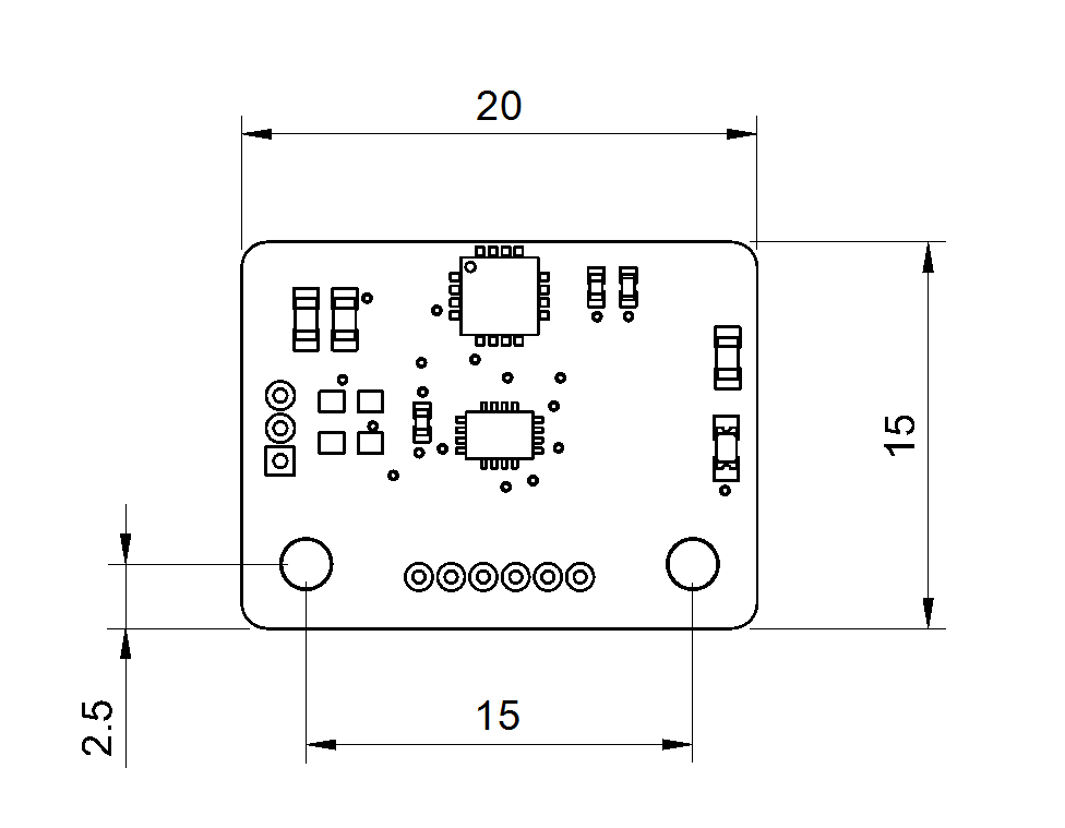
Drawing
All dimensions are in mm

Mounting Guidelines
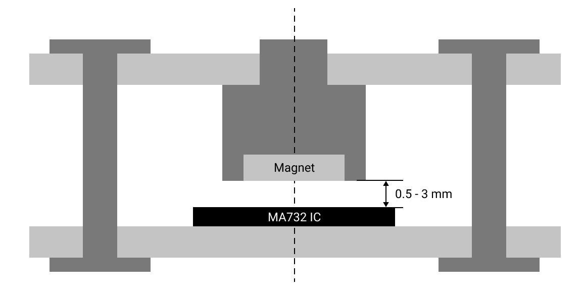
A 6 x 2.5 mm (or compatible) diametric magnet can be placed over or under the MA732 sensor and should be centered on the middle of the package with a tolerance of 0.5mm as shown in the figure below. The distance between the magnet and the package should be between 0.5-3 mm. The magnet holder must not be ferromagnetic. M2 mounting holes can be utilized for mounting the board.
 ;
;
The sensor can also be used in side mounting configuration. For more details refer MPS MA732 IC datasheet.
For off-axis configurations, we recommend using NCoder 600 due to its superior performance and lower noise levels.
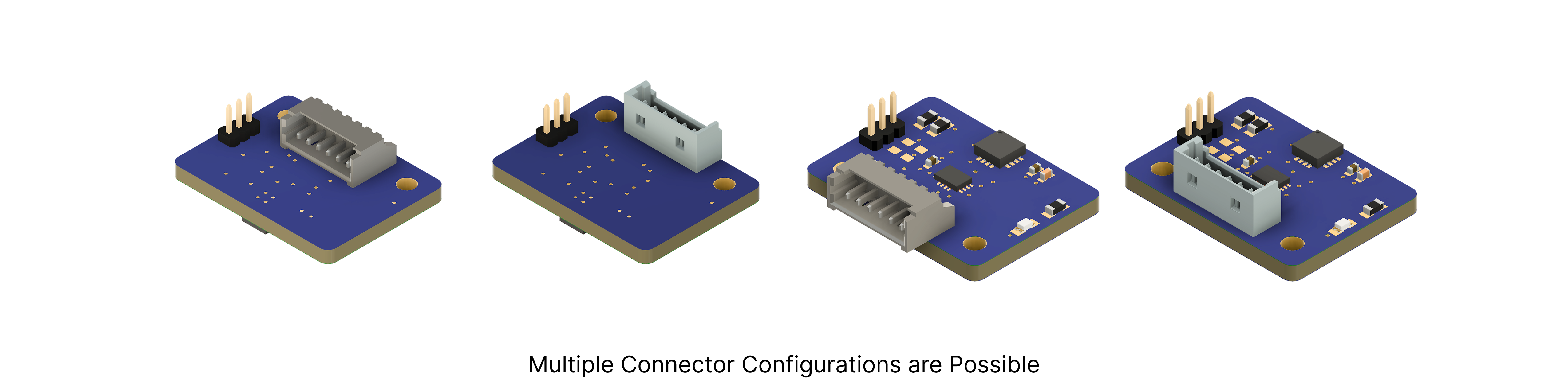
Depending on the mounting requirements, the connector can be soldered on either the top or bottom side of the board.
Operation
This board can operate in either Quadrature (ABZ) mode or SPI mode, selectable via the SEL jumper pins. When configured in ABZ mode using the SEL jumper, the encoder functions as a quadrature encoder with index, and the I/O pins can be connected to an external microcontroller to read the A, B, and Z signals. By default, the NCoder732 is set to output a 4096 CPR / 1024 PPR quadrature signal. Users can switch to SPI mode via the SEL pins to access advanced configuration options and absolute angle data. In SPI mode, the encoder exposes a 14-bit absolute angle and allows customization of parameters such as CPR via the SPI interface through the I/O connector.
For permanent configuration of the encoder mode, a 10 kΩ resistor can be soldered onto the appropriate pad: soldering it on the R4 pad sets the encoder to SPI mode, while soldering it on the R5 pad sets it to ABZ mode.
Use only 10 kΩ resistors on the pads, and ensure that resistors are not placed on both pads (R4 and R5) simultaneously, as this may cause damage to the encoder IC.
For more details on configuration and communication protocols, please refer to the MA732 datasheet.
Custom Design Service
You can contact us for a custom board based on your application requirements.