Configuration & Operation
The driver can be controlled through a CAN Bus interface. By using our NLink Adapter, it can also be connected via USB, allowing for configuration and control through the NMotion CLI Tool and NMotion Transport Library.
The API functions that can be used with the driver can be found here: NDrive Z1 API documentation
Hardware Configuration
CAN Bus Configuration
The board utilizes a daisy chainable CAN bus for control. If multiple devices are present on the CAN bus, ensure that a unique CAN Node ID is assigned to the driver. The allowable values of CAN Node ID is in the range of 0 to 127. The default CAN Node ID is 0 and must be modified to avoid communication conflicts.
The board also supports configuring the CAN bus baud rate, allowing it to operate with different CAN network speeds as required by the application. Ensure that all devices on the CAN network are configured to use the same baud rate for reliable communication.
Setting the CAN Node ID causes the driver to automatically disconnect and reconnect. Similarly, changing the CAN bus baud rate takes effect immediately and the driver will begin communicating at the newly configured baud rate. If an NLink Adapter is being used, ensure that its CAN bus baud rate is also updated to match the driver's baud rate; otherwise, communication with the driver will be lost.
To retain the configured CAN Node ID and CAN bus baud rate after a device reboot, you must save the configuration.
The API functions involved in this configuration are as follows:
Power Configuration
Voltage Trigger Levels
The board features undervoltage and overvoltage protection mechanisms to ensure the safe operation of the driver and other components. If the bus voltage drops below the undervoltage threshold or exceeds the overvoltage threshold, the driver will enter idle mode and generate a DC_BUS_UNDER_VOLTAGE or DC_BUS_OVER_VOLTAGE error, respectively.
By default the under voltage level is set to 10 V and the over voltage level is set to 56 V.
The API functions involved in this configuration are as follows:
Brake Resistor and Maximum Regeneration Current Trigger Level
The board integrates a chopper circuit for braking, enabling the connection of an external brake resistor. If a brake resistor is used, its resistance value must be configured. Additionally, the amount of current to be dumped into the power bus can be specified, with the remaining current being dissipated through the brake resistor. This ensures that the power supply remains protected from excessive current dumping.
It is recommended to use a brake resistor when powering the driver with a power supply that does not support power dumping. In the case of battery power, regenerative braking allows the battery to recharge itself by utilizing the reverse current.
Ensure a properly rated power resistor is used for dumping regenerative currents, as an incorrectly rated resistor may fail during operation.
If the regeneration current exceeds the configured maximum limit, the driver will enter idle mode and generate a DC_BUS_OVER_REGEN_CURRENT error. This condition can arise from either a saturated brake resistor or excessive current dumping into the power bus when the brake resistor is disabled.
Saving the configuration is necessary for the brake configuration to take effect in the driver.
The API functions involved in this configuration are as follows:
Motor Configuration
The driver requires specific motor parameters to ensure proper operation:
- Motor Type: Determines the control and sensing parameters used by the driver. The default motor type is
HIGH_CURRENT_BLDC, which is suitable for most low-resistance, high-current brushless motors. When using a gimbal motor or any motor with a relatively high phase-to-phase winding resistance, the motor type should be configured asGIMBAL. - Pole Pair: This value is crucial for accurate phase energization. Incorrect configuration may result in a CPR_POLEPAIRS_MISMATCH error during calibration.
- kV Rating: This value is used to calculate the torque constant, which in turn determines the torque output of the motor.
Additionally, the motor's current limit (in Amperes) must be appropriately set to prevent excessive current draw and potential damage. A CURRENT_LIMIT_VIOLATION error will be triggered if the motor current exceeds the configured limit. To maintain optimal motor performance and minimize noise in the current sensing circuit, it is recommended to avoid setting the current limit above 60A.
The API functions involved in this configuration are as follows:
Position Feedback Configuration
The controller supports multiple feedback configurations, including sensorless control, single encoder, and dual encoder modes.
In encoder-based control modes, one feedback source must be configured as the motor encoder to provide rotor position feedback for commutation and control. The motor encoder can be:
- The onboard absolute encoder
- An external incremental encoder
- An external SPI-based absolute encoder
- Hall sensors (motor encoder only)
When using dual encoder mode, an additional encoder can be configured as an output encoder (optional) for output shaft position feedback. The output encoder can be:
- The onboard absolute encoder
- An external incremental encoder
- An external SPI-based absolute encoder
For encoder configuration:
- Absolute encoders require the encoder resolution to be configured (number of possible values 2bits).
- Incremental encoders require the CPR (Counts Per Revolution) value and index usage configuration.
- Hall sensors can only be used as the motor encoder and provide an effective resolution of (6 × motor pole pairs) counts per mechanical revolution.
The resolution of the onboard encoder is fixed to 14 bits and cannot be changed.
Incorrect encoder configuration can cause calibration to fail and may result in a CPR_POLEPAIRS_MISMATCH error during motor calibration.
The configuration for different encoders are as follows:
| Encoder Type Value | Encoder Type | Description |
|---|---|---|
| 0 | TYPE_NONE | Using no encoder |
| 1 | TYPE_ONBOARD_ENCODER | Using onboard absolute encoder (Tested) |
| 2 | TYPE_INCREMENTAL | Using External incremental Encoder (Tested) |
| 3 | TYPE_SPI_ABS_AMS | Using AS5047P absolute encoder from AMS (Tested) |
| 4 | TYPE_SPI_ABS_MAXXX | Using MA7xx series absolute encoders from Monolith Power Systems (Tested with MA732, MA702) |
| 5 | TYPE_SPI_ABS_MUXXX | Using MU series absolute encoders from iC-Haus (Tested with MU150, MU200) |
| 6 | TYPE_SPI_ABS_CUI | Using AMT 203 absolute encoder from CUI (Tested) |
| 7 | TYPE_SPI_ABS_AEAT | Using AEAT absolute encoders from Broadcomm (To be tested) |
| 8 | TYPE_SPI_ABS_RLS | Using RLS absolute encoders from Renishaw (To be tested) |
| 9 | TYPE_SPI_ABS_MA600 | Using MA600 series absolute encoders from Monolith Power Systems (Tested) |
| 20 | TYPE_HALL_SENSOR | Using Hall Sensor Feedback (Tested) |
In case you have a gearbox connected to the motor and the output encoder is connected to the gearbox output, then we can configure the gear ratio in the driver itself. This will relate the output encoder and the motor encoder values with that gear ratio. The default value of gear ratio is set to 1.
Saving the configuration is necessary for the encoder configuration to take effect in the driver.
The API functions involved with this configuration are as follows:
Driver.configureMotorEncoder(encoder_type: int, resolution_param: int, use_index: bool)Driver.getMotorEncoderConfiguration()Driver.configureOutputEncoder(encoder_type: int, resolution_param: int, use_index: bool)Driver.getOutputEncoderConfiguration()Driver.disableOutputEncoder()Driver.getHallEncoderState()Driver.getHallEncoderStateCounts()Driver.setGearBoxParameters(gear_ratio: float)Driver.getGearBoxParameters()
Calibration Configuration
Before running the motor, the driver needs to do a calibration step. In this step the driver estimates the phase parameters of the motor and finds the motor encoder offset parameters.
If no encoders are being configured, then only the motor phase parameter calibration is performed.
It is crucial that the encoder(when used) and motor configuration is done properly before running calibration or it will throw errors such as CPR_POLEPAIRS_MISMATCH. The motor and encoder parameters are crucial for properly controlling the motion of the motor.
For calculating the phase parameters, calibration_voltage and calibration_current values are used. The default value for calibration_voltage is 5V and calibration_current is 5A. The maximum resistance of the motor which the driver can measure is given by the value of calibration_voltage/calibration_current (so for the default case, the driver will be able to measure motor phase resistances upto 1Ω). In case the resistance of the motor falls outside the measurable range of the driver, the driver will throw a PHASE_RESISTANCE_OUT_OF_RANGE error during calibration. To overcome this, one needs to change the value of calibration_voltage or calibration_current to increase the range of resistance the driver can measure (increasing calibration_voltage or decreasing calibration_current will increase the range). Considering the inductance, make sure that the phase inductance value of the motor is between 2 µH and 4000 µH, or else the driver will throw a PHASE_INDUCTANCE_OUT_OF_RANGE error during calibration.
If the above method fails even after multiple attempts, it is possible to manually set the motor phase resistance and inductance values directly in the driver.
During the calibration process, the motor will automatically rotate in both clockwise and counterclockwise directions. Ensure the motor and any attached mechanism can move freely and that the surrounding area is clear of obstructions before starting calibration.
The API functions involved in this configuration are as follows:
Thermal Limit Configuration
The board uses an onboard NTC thermistor to measure the driver's temperature during the operation. The configuration for thermal limiting using this on-board thermistor cannot be changed, the driver will start limiting the current once the board temperature reaches 110°C. When the board temperature reaches 120°C, it will turn off the power to the motor and will set the error to FET_THERMISTOR_OVER_TEMP. If this limit is being reached, then it is suggested to add an active cooling mechanism to the MOSFETs on the board which will help to keep the temperature in safe levels during the operation.
Additionally, the board also supports an external motor NTC thermistor that can be used to limit the motor currents when the motor temperature goes beyond a safe limit. If the external motor thermistor is connected then one needs to configure the r_ref value (resistance at 25°C), beta value (Temperature coefficient of resistance) and the upper_limit value (in °C). The current limiting will start when the temperature reaches a value of upper_limit - 10 (in °C). When the motor temperature reaches the upper_limit value, the driver will turn off the power to the motor and will set the error to MOTOR_THERMISTOR_OVER_TEMP . If this limit is being reached, additional cooling is recommended to help maintain the motor's temperature within safe limits during operation.
The API functions involved in this configuration are as follows:
Startup Configuration
This can only be configured after running the full calibration sequence at least once and saving the configuration. Setting startup configuration without setting all other motor and encoder parameters would cause the driver to throw errors.
The driver supports configuring startup events that should automatically happen once the driver starts. It supports these events
- Start motor encoder index search on startup. This is only applicable when an incremental encoder is being used as a motor encoder.
- Start encoder matching on startup to make sure that the output encoder and motor encoder is matched after the driver turns on. This is only applicable when an output encoder is properly configured.
- Go into a particular control mode when the driver starts up. The control mode will depend on the mode in which the configuration to the driver was last saved. However, the commanded values within the selected control mode are not retained. For example, if the driver was saved in position control mode with the motor set to a specific position, it will start in position control mode but remain at the current position without moving to the previously set position. Similarly, if saved in velocity control mode, the driver will start with velocity control enabled and a commanded velocity of zero, rather than resuming any prior velocity. This behavior also applies to current control mode, where the driver will start with a commanded current of zero.
The API functions involved in this configuration are as follows:
Controller Configuration
The controller in the driver is a cascading style controller with cascaded position, velocity and current control loops. When the control mode is set to position control or trajectory control, all of the cascaded controller runs. When running in velocity control mode, the position control part is removed and the velocity command is directly given to the velocity controller. Similarly, in torque control mode, only the current controller loop runs.
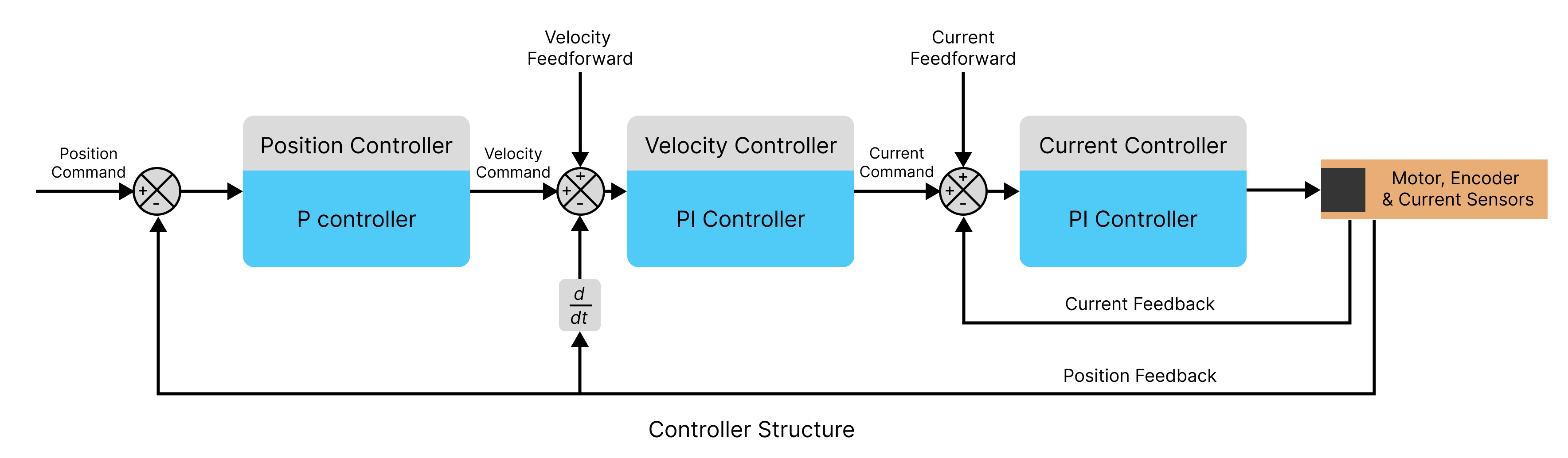
The controllers used in each of the loops is a variation of PID Controllers
Position Control Loop
Its a proportional controller with a single gain value (pos_gain). The output of the controller, velocity_command is calculated as follows:
velocity_command = pos_gain * (position_command - position_feedback) + velocity_feedforward
Velocity Control Loop
Its a proportional-integral controller with a single gain value (vel_gain) and a single integrator gain (vel_integrator_gain). The output of the controller, current_command is calculated as follows:
vel_integral += vel_integrator_gain * (velocity_command - velocity_feedback)
current_command = vel_gain * (velocity_command - velocity_feedback) + (vel_integral) + current_feedforward
Current Control Loop
Its a proportional-integral controller with a single gain value (current_gain) and a single integrator gain value (current_integral), the gain values of this loop is calculated based on the motor's phase parameters (phase resistance and phase inductance) and a current controller bandwidth parameter.
current_gain = current_control_bandwidth * motor_phase_inductance
current_integrator_gain = current_gain * (motor_phase_resistance / motor_phase_inductance)
current_integral += current_integrator_gain * (current_command - current_feedback)
motor_command = current_gain * (current_command - current_feedback) + current_integral
The gain values of the loop can be changed according to the needs of the application. If the gains cause an instability in the system, then the driver will throw a UNSTABLE_CONTROLLER_GAIN error.
The API functions involved in this configuration are as follows:
Driver.setPositionControllerGain(position_gain: float)Driver.getPositionControllerGain()Driver.setVelocityControllerGains(vel_gain: float,vel_integrator_gain: float)Driver.getVelocityControllerGains()Driver.getCurrentControllerGains()Driver.setCurrentControllerBandwidth(bandwidth: float)Driver.getCurrentControllerBandwidth()
Saving Configuration
Upon completing the configuration process, the settings can be saved to the driver's non-volatile memory. This ensures that the configurations are retained even after a power cycle or device restart. Saving the configuration will trigger an automatic device reboot.
The following configurations in the driver are saved:
- CAN Bus Configuration : CAN Node ID & CAN Baud Rate of the Device.
- Power Configuration : Voltage trigger levels (under voltage and over voltage trigger levels), Brake resistor enable/disable status, Brake resistor value, Maximum regeneration current trip level.
- Motor Configuration: Motor Pole pair, KV rating and current limit values.
- Encoder Configuration: Motor Encoder parameters (type, resolution parameter & use_index flag), Output Encoder parameters (type, resolution parameter & use_index flag) and Gearbox ratio.
- Calibration Configuration: Motor calibration voltage, Motor calibration current and Post-Calibration Parameters (motor encoder offset value, phase resistance and phase inductance).
- Thermal Limit Configuration: Motor Thermistor Parameters (r_ref and beta) and Thermal upper limit.
- Startup Configuration: All the flags to set the events on startup: index_search, encoder_matching and closed_loop.
- Controller Configuration: Control Loop parameters (position gain, velocity gain, velocity integrator gain, current controller bandwidth) & Control Mode without the commanded value.
The configuration data is stored in the microcontroller's onboard EEPROM memory. To prolong the memory's lifespan, it is recommended to limit the frequency of configuration updates, as EEPROMs have a finite number of write cycles.
The API functions involved in this configuration are as follows:
Operation
Connection
The board uses a CAN bus to retrieve data and send commands to the driver. The driver can be controlled either through a native CAN interface or connected to a PC via USB using an NLink Adapter. Regardless of the interface used, the NMotion Transport Library can be used to control the driver.
Calibration
Before operation it is necessary to do the calibration step in which the driver finds out the motor phase and motor encoder offset parameters required for the motion of the motor. If no encoders are being configured, then only the motor phase parameter calibration is performed and no encoder-related calibration steps are required. In case the motor encoder is an incremental one, then the driver will perform an index search and then do an offset calibration. In case the motor encoder is an absolute one, then the driver will only perform an offset calibration.
If an incremental encoder is configured as a motor encoder and the configuration is saved after calibration, an index search is necessary upon each device reboot. If the configuration is not saved, then the entire calibration sequence must be repeated after every reboot. However, if an absolute encoder is configured as the output encoder and the configuration is saved after calibration, no further calibration procedures are required upon device reboot.
When both input and output encoders are configured, an encoder matching cycle is recommended. This step synchronizes the motor encoder and output encoder, ensuring accurate position tracking and preventing unintended motion. The control loops utilize the motor encoder and gearbox ratio to compute the final output position, making encoder synchronization crucial.
If the driver is unable to estimate the motor phase parameters, the user can manually configure these values in the driver and proceed by running only the encoder calibration to complete the calibration process.
The API functions involved with calibration step are as follows:
MAxxx Off Axis Calibration
When an MAxxx series encoder is used in a side-shaft or off-axis magnetic target configuration, the magnetic field observed by the sensor can become nonlinear with respect to the mechanical angle, resulting in position measurement errors. To compensate for these effects, the driver performs an off-axis calibration procedure while the encoder rotates at a constant speed, measuring the position error over multiple revolutions and computing the required correction parameters.
For MA702 and MA732 encoders, the calibration process performs BCT calibration only. For MA600 encoders, the calibration process performs both BCT calibration and Harmonic Compensation calibration, providing additional correction for position errors caused by magnetic target misalignment, eccentricity, and other installation-related effects.
For best results, perform this calibration after the final mechanical assembly is complete and save the configuration once calibration has successfully finished.
Use sensorless or open-loop control mode of the driver to rotate the motor at a constant velocity before starting the off-axis calibration procedure.
The API functions involved with MA600's off axis calibration are as follows:
Control Modes
The driver supports various control modes. Depending on the selected mode, the control reference frame can be based on either the actuator output or the motor shaft. For output-referenced modes, the driver computes the output position and velocity using the motor encoder feedback and the configured gearbox ratio. For sensorless modes, control is performed using internally estimated motor states without requiring encoder feedback.
The different control modes in which the driver can run are as follows:
- Idle Mode: In this mode the motor will not be in any control loop, and it will be free to turn.
- Sensorless Velocity Control Mode: The motor moves at a specified velocity without requiring encoder feedback. The driver estimates the rotor position and velocity internally and accelerates to the commanded velocity using the configured ramp rate.
- Parameters:
- Velocity (in degrees per second) at which the motor should move.
- Ramp rate (in degrees per second²) that determines how quickly the motor accelerates or decelerates to the commanded velocity.
- Current (in amperes) used by the sensorless controller to drive the motor.
- Parameters:
- Open Loop Position Control Mode: The motor moves to a specified relative position in open-loop operation without using encoder feedback. The commanded position, velocity, and acceleration are specified in electrical units that scale with the motor pole-pair count.
- Parameters:
- Position (in pole-pair units) relative to the current position. For example, with a motor of 7 pole pairs, setting position as 7 rotates the motor exactly one full revolution.
- Velocity (in pole-pair units per second) at which the motor should move.
- Acceleration (in pole-pair units per second²) used to reach the commanded velocity.
- Current (in amperes) used to maintain motor synchronization during open-loop operation.
- Parameters:
- Open Loop Velocity Control Mode: The motor rotates at a specified velocity in open-loop operation without using encoder feedback.
- Parameters:
- Velocity (in pole-pair units per second) at which the motor should rotate. A value equal to the motor pole-pair count corresponds to one mechanical revolution per second.
- Acceleration (in pole-pair units per second²) used to reach the commanded velocity.
- Current (in amperes) used to maintain motor synchronization during open-loop operation.
- Parameters:
- Position Control Mode: The motor moves at a specified velocity to a particular position as commanded.
- Parameters:
- Position (in degrees) to which the motor should move
- Velocity (in degrees per second) at which the motor should move.
- Parameters:
- Position Control Mode with Feedforward terms: The motor moves at a specified velocity to a particular position as commanded. Additionally the feedforward terms of velocity controller and torque controller can be set.
- Parameters:
- Position (in degrees) to which the motor should move
- Feedforward Velocity (in degrees per second) for the velocity controller.
- Feedforward Torque (in Nm) for the torque controller.
- Parameters:
- Velocity Control Mode: The motor moves at a particular velocity as commanded.
- Parameters:
- Velocity (in degrees per second) at which the motor should move.
- Parameters:
- Velocity Control Mode with Feedforward terms: The motor moves at a particular velocity as commanded.
- Parameters:
- Velocity (in degrees per second) at which the motor should move.
- Feedforward Torque (in Nm) for the torque controller.
- Parameters:
- Torque Control Mode: The motor current is controlled so that a particular amount of torque remains applied as commanded. The motor velocity is also limited during this motion. Once the motor reaches the maximum motor velocity then it will start limiting the motor currents to make sure the velocity remains in the specified range.
- Parameters:
- Torque value (in Newton-meter) which the motor should supply.
- Maximum velocity limit (in degrees per second) at which the motor should move.
- Parameters:
- Trapezoidal Trajectory Control Mode: The motor moves to a particular position in a trapezoidal trajectory pattern as commanded.
- Parameters:
- Position (in degrees) to which the motor should move.
- Max velocity (in degrees per second) of the motor that it should reach during the motion.
- Acceleration rate (in degrees per second2) of the motor which decides how fast the motor should reach the max velocity.
- Deceleration rate (in degrees per second2) of the motor which decides how fast the motor should reach the zero velocity.
- Parameters:
- S-curve Trajectory Control Mode: The motor moves to a particular position in a S-curve trajectory pattern as commanded.
- Parameters:
- Position (in degrees) to which the motor should move.
- Max velocity (in degrees per second) of the motor that it should reach during the motion.
- Acceleration rate (in degrees per second2) of the motor which decides how fast the motor should reach the max velocity.
- Jerk rate (in degrees per second3) of the motor which decides how fast the motor should reach the max acceleration.
- Parameters:
- Velocity Ramp Control Mode: The motor moves at a specified velocity as commanded. But the specified velocity is reached with a slow ramp as specified by the ramp rate.
- Parameters:
- Max velocity (in degrees per second) at which the motor should move.
- Ramp rate (in degrees per second2) of the motor which decides how fast the motor should accelerate/decelerate to reach that commanded max velocity value.
- Parameters:
- Torque Ramp Control Mode: The motor applies the commanded torque, but the target torque is reached gradually according to the configured torque ramp rate. A velocity limit can also be specified to restrict the maximum motor speed while generating torque.
- Parameters:
- Target torque (in Nm) to be applied by the motor.
- Torque ramp rate (in Nm/s) that determines how quickly the motor torque increases or decreases to reach the commanded target torque.
- Velocity limit (in degrees per second) that restricts the maximum motor speed during operation.
- Parameters:
setTrajectoryControl() function in firmware version 0.3.1 is renamed to setTrapezoidalTrajectoryControl()
The API functions involved for this control modes are as follows:
Driver.setDeviceToIdle()Driver.setDeviceToActive()Driver.setSensorlessVelocityControl(self, degrees_per_seconds: float, ramp_rate_degrees_per_second: float, current: float)Driver.setOpenLoopPositionControl(self, pos: int, vel: int, accel: int, current: float)Driver.setOpenLoopVelocityControl(self, vel: int, accel: int, current: float)Driver.setPositionControl(angle: float, degrees_per_seconds: float)Driver.setPositionControlWithFeedForward(angle: float, velocity_ff: float, torque_ff: float)Driver.setVelocityControl(degrees_per_seconds: float)Driver.setVelocityControlWithFeedForward(degrees_per_seconds: float, torque_ff: float)Driver.setTorqueControl(torque: float, degrees_per_second: float)Driver.setTrapezoidalTrajectoryControl(angle: float, degrees_per_seconds: float, accel_rate: float, decel_rate: float)Driver.setScurveTrajectoryControl(angle: float, degrees_per_seconds: float, accel_rate: float, jerk_rate: float)Driver.setVelocityRampControl(degrees_per_seconds: float, ramp_rate_degrees_per_second: float)
Zero Position
The driver supports setting the current motor position as zero. When an absolute encoder is available, the driver can determine the position reference immediately after power-up and retain a consistent zero position across reboots. If an absolute encoder is configured as the output encoder, it will be used for this purpose. Otherwise, the driver will use an absolute encoder configured as the motor encoder.
When using an incremental encoder or Hall sensors, the driver cannot determine the absolute position after a reboot. In these cases, the current position can still be set as zero after the driver has completed its startup and calibration procedures, but the zero position must be re-established each time the device powers up.
Saving the configuration after setting the zero position preserves the configured position offset across reboots. When an absolute encoder is available, this allows the driver to restore the same zero position after power-up. When using an incremental encoder or Hall sensors, the encoder position is reset on reboot, so the saved offset is applied to an unknown reference position and the reported position may no longer correspond to the previously configured zero position.
The API functions involved with setting the zero position are as follows:
Getting Other Datapoints
The driver includes a multitude of onboard sensors and it offers support for other external sensors. It also has various software states that determine the operation of the motor. There are specific API functions that can be used to get sensor data and different software states from the driver.
The API functions involved with getting various data points are as follows:
Versioning
Encoder Data
Driver.getOutputPosition()Driver.getOutputVelocity()Driver.getOutputAcceleration()Driver.getOutputTorque()Driver.getMotorPosition()Driver.getMotorVelocity()Driver.getMotorAcceleration()Driver.getMotorTorque()Driver.getMotorEncoderRawData()Driver.getOutputEncoderRawData()
Temperature
Electrical
Driver.getBusVoltage()Driver.getBusCurrent()Driver.getIdqCurrents()Driver.getMotorPhaseCurrents()Driver.getMotorPhaseParameters()Driver.getBrakeCurrent()
Miscellaneous
Error Handling
During operation there are cases in which the driver will throw an error in case of wrong configuration or other operational scenarios. When the driver throws an error, the Error LED will turn ON and then the motor will be set to an idle state. During this time, driver is able to return an error code value for the errors. The value of which can be looked up in the below table to find out what the error means and how to solve it.
When the driver throws an error, the error needs to be manually cleared before the motor can normally run, if the errors are still not cleared then driver reboot would be necessary.
| Error Code | Error | Reason | Troubleshooting |
|---|---|---|---|
| 1 | DC_BUS_UNDER_VOLTAGE | Bus voltage drops lower than the under voltage trip level. Could be caused when the motor is trying to draw more current than what the power supply can give. | Check the cause of the drop in bus voltage, then adjust the under-voltage trip level if needed. |
| 2 | DC_BUS_OVER_VOLTAGE | Bus voltage goes higher than the over voltage trip level. Could be caused when the dumped regeneration current to the supply is too high, and the supply is not able to handle it. | Check for the cause of the spike in bus voltage, and then adjust the over-voltage trip level if needed. If the cause of spikes is attributed to regeneration current, use an appropriate brake resistor to divert more current through the resistor. |
| 3 | DC_BUS_OVER_REGEN_CURRENT | Regenerative current goes higher than the maximum regen current trip level | Change the trip level value if more current can be dumped via brake resistor, if not find an appropriate brake resistor with the required specifications. |
| 5 | INVALID_STATE | Driver state is invalid, Possibly caused when motor is set to closed loop control without running calibration | Make sure to run the calibration step before putting the motor in closed loop control |
| 6 | ESTOP_REQUESTED | Received emergency stop signal from user | Clear errors and continue. |
| 7 | PHASE_RESISTANCE_OUT_OF_RANGE | Phase resistance is out of range | Set calibration current and calibration voltage such that the phase resistance is in the measurement range |
| 8 | PHASE_INDUCTANCE_OUT_OF_RANGE | Phase inductance is out of range | Check if the phase inductance value of the motor is between 2 µH and 4000 µH |
| 9 | DRV_FAULT | Low level driver fault | - |
| 10 | FOC_ERROR | Low level control loop fault | - |
| 12 | CURRENT_LIMIT_VIOLATION | Motor current goes higher than the current limit | Check why the motor is drawing too much current, and if necessary, increase the current limit while ensuring it remains safe for the motor. |
| 13 | MOTOR_THERMISTOR_OVER_TEMP | Motor temperature is higher than the upper limit | Actively cool the motor during operation, and if needed, increase the temperature upper limit while ensuring it remains safe for the motor. |
| 14 | FET_THERMISTOR_OVER_TEMP | Driver temperature reaches 120 °C | Actively cool the driver during operation. |
| 16 | UNKNOWN_PHASE_ESTIMATE | Phase estimate errors, Possibly caused when motor is set to closed loop control without running calibration | Make sure to run the calibration step before putting the motor in closed loop control |
| 17 | UNBALANCED_PHASES | Considerable amount of difference between phase inductance and phase resistance values between each phases | Check if the phase A, B and C connections from the motor is proper, Check if the phase coils of the motor is damaged. |
| 19 | UNSTABLE_CONTROLLER_GAIN | Gain values of the control loop is causing instabilities | Tune the gain values properly. |
| 20 | SPINOUT_DETECTED | Mechanical slip between motor and motor encoder | Make sure that the mechanical coupling between the motor and motor encoder is proper. |
| 21 | CPR_POLEPAIRS_MISMATCH | Mismatch between resolution or CPR value of Motor Encoder and Motor pole pairs | Set the CPR / resolution parameter of the motor encoder and the pole pair values of the motor properly |
| 22 | MOTOR_ENCODER_NO_RESPONSE | There is no response from Motor Encoder | Check if the connections are fine and the motor encoder is operational. |
| 23 | OUTPUT_ENCODER_NO_RESPONSE | There is no response from Output Encoder | Check if the connections are fine and the output encoder is operational. |
| 24 | OUTPUT_ENCODER_CPR_ERROR | Mismatch between actual CPR/resolution and configured CPR/resolution | Set the CPR / resolution parameter of the output encoder properly. |
| 25 | UNSUPPORTED_ENCODER_MODE | Configured motor and output encoder is not supported | Set a properly supported encoder type. |
| 26 | INDEX_NOT_FOUND_YET | Unable to find index of incremental motor encoder | Check if the incremental encoder is operational and if the index pin of the encoder is properly connected to the driver |
| 27 | ABS_SPI_TIMEOUT | Encoder SPI communication error | Check if a compatible absolute encoder is being used and check SPI connection |
| 28 | ABS_SPI_COM_FAIL | Encoder SPI communication error | Check if a compatible absolute encoder is being used and check SPI connection |
| 29 | ABS_SPI_NOT_READY | Encoder SPI communication error | Check if a compatible absolute encoder is being used and check SPI connection |
| 30 | HALL_ILLEGAL_STATE | Hall Sensor Feedback error | Check if Hall sensor connections are okay. Check if pull up and filter capacitors are properly placed and is close to the board |
| 255 | UNKNOWN_ERROR | Unknown Error | - |
If you continue to face any other errors or errors even after following the troubleshooting step, make sure to reach out to us.
The API functions involved with error handling are as follows: