NDrive Z1 Quick Setup
In order to show how a motor can be easily connected and used with the driver, we are assuming that we have a 24V 1:6 planetary geared BLDC motor actuator. The specifications of the actuator which is required to configure the driver are as follows:
- Nominal Voltage: 24 V
- Gear ratio: 6
- KV rating: 90
- Rated Current: 8 A
- Peak Current: 20 A
- Motor Pole Pairs: 14
- Phase Inductance: 500 µH
- Phase Resistance: 420 mΩ
- Rated Speed: 2000 rpm
- Maximum Motor Temperature: 120 °C
- Inbuilt motor NTC thermistor specifications: Resistance at 25°C is 10 kΩ, Beta constant is 3300.
The specifications of encoders and brake resistor which we are using with the driver are as follows:
- Brake Resistor: 2Ω resistance and is rated for 50 Watts.
- Motor Encoder: Onboard Absolute Encoder on the driver will be configured as a motor encoder.
- Output Encoder: An external MU150 Encoder at the output of the actuator will be configured as an output encoder.
We will be using NLink Adapter to connect the driver to PC running NMotion CLI tool in Linux (note there won't be any changes in the Windows case as well). We will use the tool to configure and run the motor.
Connection
- Connect the three phases A,B and C of the motor to the Power Pad Connections, the order of the phase connections does not matter.
- Since we are using a benchtop power supply unit, it would not be able to handle too much of regenerative currents. Therefore one needs to connect the brake resistor to the required terminals and then configure it.
- Use a terminal and plug in the motor wires and brake resistor wires first. Then one can solder the phase wires as well. Make sure the polarity is same and the driver is not hot-plugged.
- Connect the MU150 absolute encoder to the absolute encoder interface.
- Plug in the CAN Bus connections and connect this to NLink Adapter and then connect the Adapter to PC's USB Interface.
CLI Tool Setup
Start the NMotion CLI tool, and plug in your NLink Adapter.
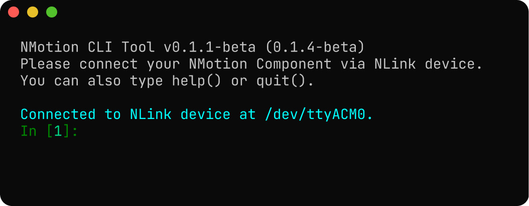
Now turn on your power to the driver.
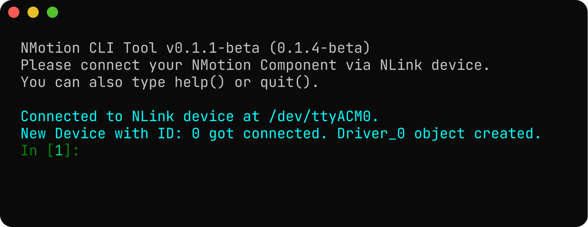
Now you can use the Driver_0 object to call the relavant Driver APIs in Python to run and configure the driver.
Configuring the Driver
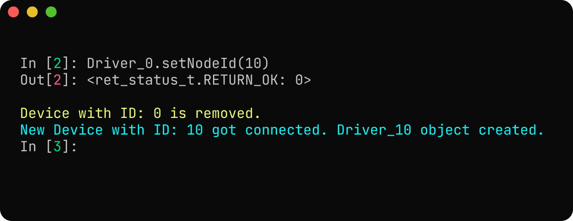
- CAN Bus Configuration : Update the CAN Node ID of the driver from default value of 0 to 10. On setting the CAN Node ID the driver will automatically reboot, which will make the
Driver_0object to be deleted automatically and creata a newDriver_10object for the driver.
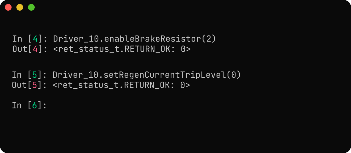
- Power Configuration : Since we are using a 24V actuator, the default values of under voltage trigger level (10 V) and over voltage trigger level (56 V) is fine. A brake resistor needs to be connected and configured. We will set the maximum regeneration current trigger level to 0 A, meaning that the entire regeneration current will be directed to the brake resistor.
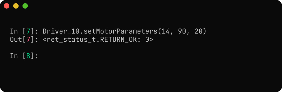
- Motor Configuration : Set the pole pairs, KV rating and current limit of the motor.
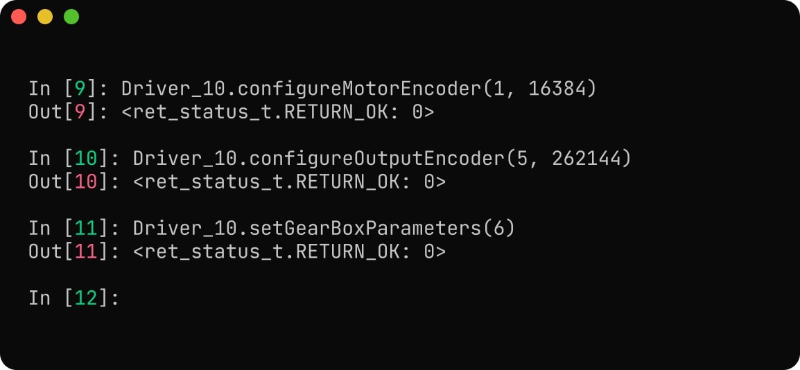
- Encoder Configuration : Configure the motor encoder to be of onboard absolute type and the output encoder to be of MU150 SPI type.
For the motor encoder, we are setting the resolution to 14 bits and hence the value of resolution parameter will be
16384(214 = 16384). For the output encoder, we are setting the resolution to 18 bits and hence the value will be262144(218 = 262144). Since both of them are absolute type, there won't be any use_index parameter for both. Also we know that there is a gearbox attached to the motor, hence set the gearbox ratio of the motor to 6.
-
Calibration Configuration : The default values are set in such a way that we can measure motor phase resistances upto 1Ω, and therefore no changes will be required here.
-
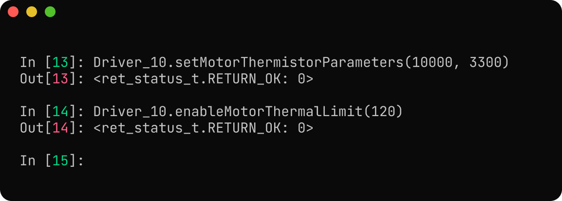
Thermal Limit Configuration : Set the thermistor parameters and set the upper limit for the motor temperature.
- Save Configuration : After configuring all the parameters we need to do a save configuration call to make sure all the parameters are set.
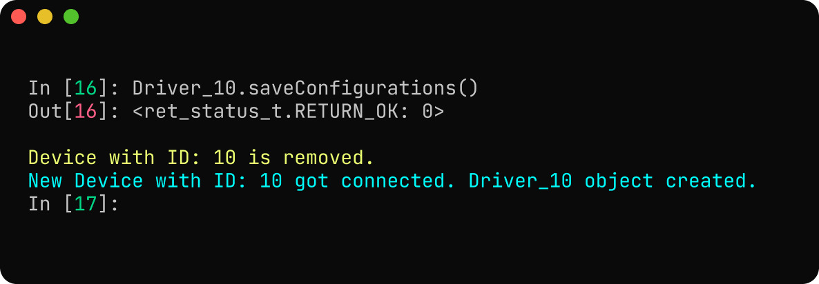
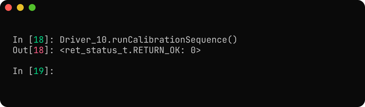
Calibration
- Calibration : Start the callibration of the motor.
-
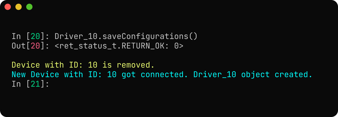
Startup Configuration : Here no startup configuration is necessary.
-
Save Configuration : After setting the startup configuration, it is better to save the configuration and let the driver reboot.
Running the Motor
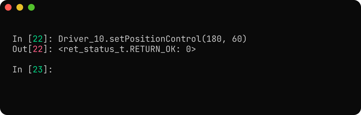
Since we are using an absolute encoder as motor encoder, we don't require to do any index search or calibration procedures, we can directly operate the motor. The motor can be run in various control modes as necessary. Here, we will be running the motor to a position of 180 degrees at a velocity of 60 degrees per second.
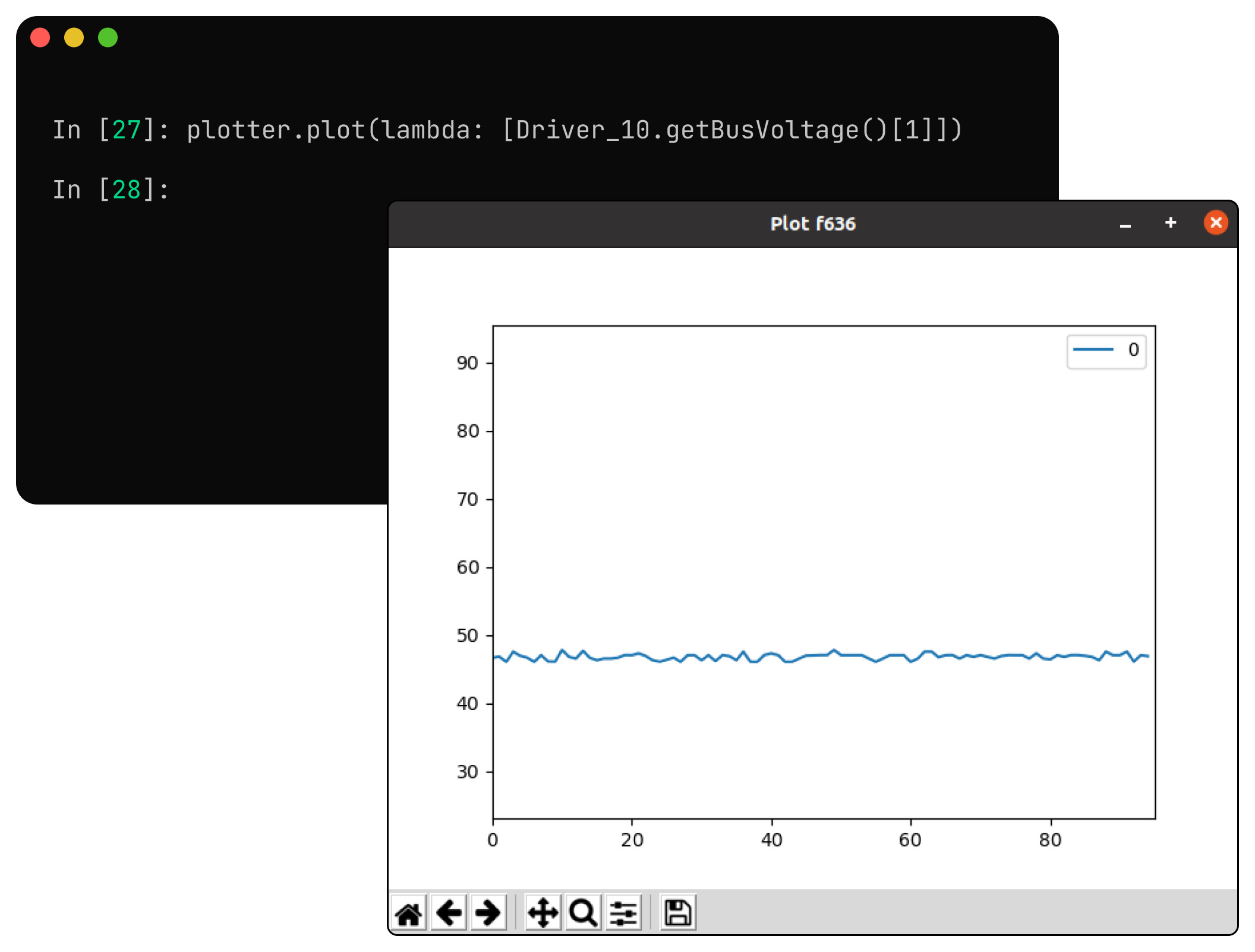
One can also plot the real-time data using the CLI tool as well.
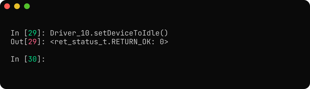
Shutting Down
To shut down the motor properly, we can command the motor to come to an idle state and then we can safely turn OFF the driver afterwards.