Hardware
Pinouts
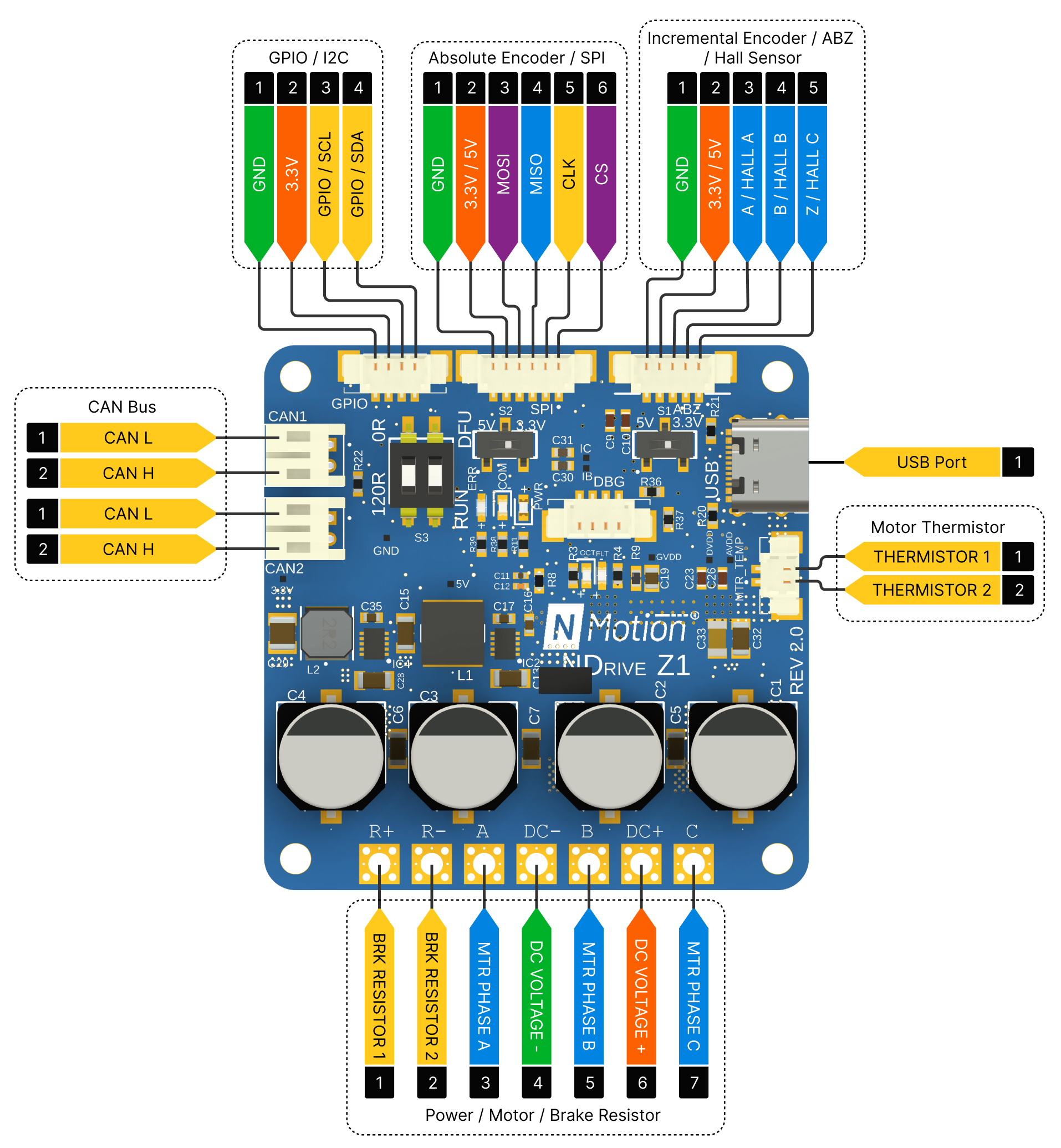
All pins are 3.3V tolerant.
Power Side Interface

This side includes connections to the motor phases, external brake resistor (if needed), and the DC power supply (12-48V). To connect, you may either solder the wires directly to the designated pads or utilize a 5mm pitch terminal block. Ensure that the wires and terminal blocks are compatible with the motor's current rating.
- DC power input pins can't tolerate reverse polarity, please verify all power connections before energizing the driver
- DC power supply line can't tolerate voltages above 56 V. Ensure that the motor's regenerative currents don't exceed 56 V on the DC power supply line by using an appropriate brake resistor to mitigate the voltage spike.
- Never hot plug the driver, make sure that the power connections are connected before turning on the power.
Motor Thermistor Interface

To enable motor temperature-based thermal limiting, connect your thermistor to the THERMISTOR 1 and THERMISTOR 2 pins on the MTR_TEMP connector. The board's integrated 3.3kΩ resistor and filter capacitor circuit on the MTR_TEMP connector facilitate this functionality. A 2-pin JST connector with a 1.25 mm pitch is suitable for connecting the thermistor.
Incremental Encoder / Hall Sensor Interface
The board supports an external incremental encoders and hall sensors through this interface. To connect an incremental encoder, wire the encoder's A, B, and Z signals to the corresponding pins on the board. For Hall sensors, connect the three Hall phase outputs (Hall A, Hall B, and Hall C) to the A, B, and Z pins of the interface. For optimal performance and noise immunity, the Hall sensor signals should include appropriate pull-up resistors and filter capacitors, with these components placed as close to the controller board as possible.


The power supply for the hall sensor or encoder can be either 3.3V or 5V, depending on the specific encoder's requirements. Configure the power supply by adjusting the switch S1. A 5-pin JST connector with a 1.25 mm pitch is suitable for connecting the incremental encoder or hall sensor.
Ensure that the connected incremental encoder's or hall sensor's current consumption does not exceed 150mA.
We do offer a Hall sensor interface board that integrates the necessary pull-up resistors and filter capacitors. Please contact us if you would like to procure one.
Absolute Encoder Interface
The board supports an external absolute encoder with an SPI interface. To utilize this feature, connect the encoder's MOSI, MISO, CLK, and CS pins to the corresponding pins on the board.


The power supply for the encoder can be either 3.3V or 5V, depending on the specific encoder's requirements. Configure the power supply by adjusting the switch S2. A 6-pin JST connector with a 1.25 mm pitch is suitable for connecting the absolute encoder.
Ensure that the connected absolute encoder's current consumption does not exceed 150mA.
CAN Bus Interface

The board features a daisy chainable CAN bus interface with two CAN ports. One port is designated for incoming CAN bus connections from the main device, while the other port is intended for connecting to the subsequent device in the bus chain. A 2-pin JST PH connector with a 2mm pitch is suitable for both CAN ports.

If the driver is the last component in the CAN bus chain, ensure that the DIP switch is configured to enable the termination resistor. Failure to do so may result in communication errors.
USB Interface
The board includes a USB port for firmware upgrades and configuring the driver (fully supported in Linux only); please reach out to us for firmware upgrades and configuring related assistance.
DIP Switch
The DIP switch configuration determines whether the onboard termination resistor is enabled and whether the microcontroller enters DFU mode.

DFU mode is intended for use only in case of flashing errors and should remain disabled by default.
LED Status Indications

The board incorporates three LEDs to indicate various operational states:
- Power LED: Turns ON when the board is powered ON.
- CAN Communication LED: Flashes to signify ongoing CAN bus communication (both incoming and outgoing data).
- Error LED: Turns ON when an error is encountered, and turns OFF when the errors are cleared.
On-board Encoder
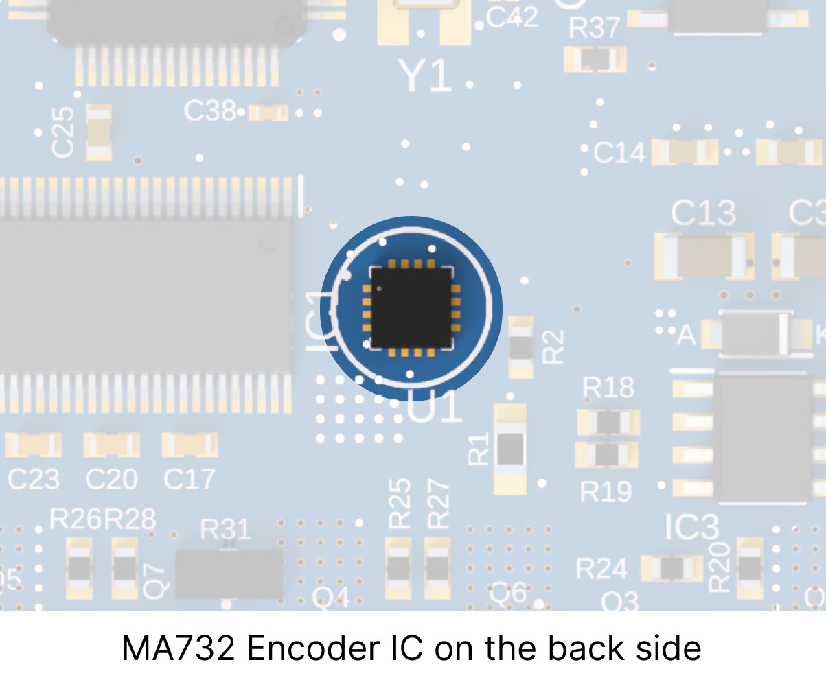
The board features an integrated MA732 encoder chip configured for absolute mode operation with a 14-bit resolution. A 6x2.5mm diametrically magnetized magnet is compatible with this encoder. For more details look into MPS Magnets and Selection Guide.
Mounting Guidelines
The board is equipped with four 3 mm (M3) mounting holes located at the corners. These holes can be used to securely mount the driver to a suitable surface. When utilizing the onboard encoder, ensure that the encoder IC and the magnet are placed on the same rotational axis with a distance of at most 1 mm between the IC's surface and the magnet.
Drawing
All dimensions are in mm


Download the CAD file for the driver here: NDrive-Z1 2.0 48V